| |||||||||
|

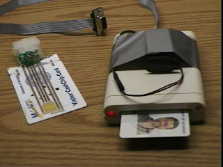
The device on the left is a standard smart card (in this case, UM Cash Chip card)
with taps on the contacts brought out to a standard Molex connector. The card can
be inserted in a device and the dialog between the card and the device monitored
at the connector.
The device on the right is a smart card reader/writer, battery powered for
portability.

Laboratory setup for smart card experiments. On the left is a smart card
reader with a tap for monitoring the I/O pin. While the NT machine in the
background is talking to the card, a separate OpenBSD machine (not pictured)
monitors the transactions.

Close-up of the smart card reader. This is a commercial device, slightly
modified. It consists of a 3.58 MHz clock, some reset circuitry, rs-232
level converters, and a smart card socket.

Close-up of the snooping circuitry. At the left is the underside of the
commercial smart card reader showing connections to the ground and I/O pins
(contacts 5 and 7 on the card). At upper left is the snooping circuit,
which consists of a max232 inverter and level converter, voltage regulator,
and associated components. For field work this fits conveniently in a 35mm
film can and everything can be powered off 9 volt batteries. The circuit
connects to the serial port on a notebook computer running OpenBSD.

Field setup for smart card experiments. The card reader is on the left, the
snooping circuit is in the film can at the front, and the tapped card is
inserted in the vending machine. The notebook computer runs OpenBSD with
disconnected AFS.

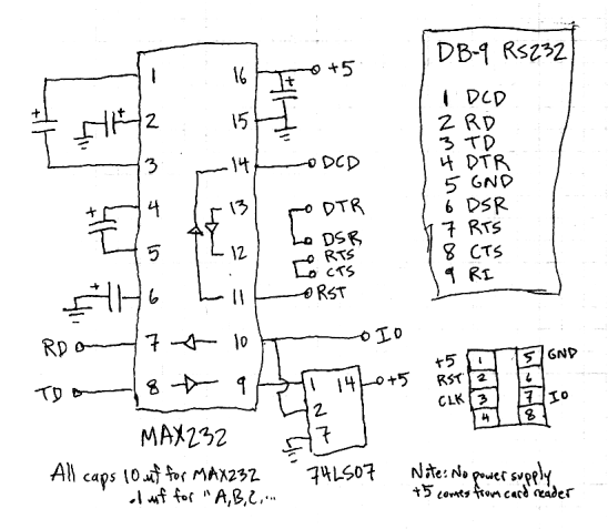
Schematic of the snooping circuit.
The 74LS07 can be omitted for passive snooping.
|
 |

